Five Minute Facts About Packet Timing
By Doug Arnold.
One-step or two-step clocks for IEEE 1588? This is a question I hear a lot. If you are designing PTP enabled equipment, then it is a question, which has important ramifications for the architecture of your device. However, if you are buying PTP enabled equipment and integrating them into a network, it doesn’t matter at all. Furthermore, for the network architect, it doesn’t even matter if you mix one-step and two-step devices in the same network. Let me explain how one-step is different from two-step, and what the IEEE 1588 standard requires of devices, and my statements above will, hopefully, become clear.
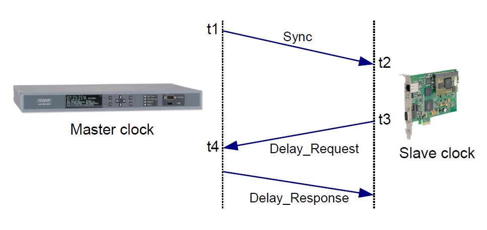
The short version of how one and two-step clock work is just this: for any PTP event message, that is one which gets timestamped, the message either gets an accurate timestamp placed in the message on-the-fly as it is about to leave the device (one-step), or a second message carries the accurate timestamp (two-step). In the case of delay requests, a second message is required regardless since the timestamp has to be sent from one device to another, but sync messages, and peer delay response messages can be either one or two-step. Consider the message sequence diagram below depicting one-step end-to-end operation.
Note that this is simpler than the one depicted in the earlier post Why is 1588 so accurate? which describes two-step operation. There is no need for a follow up message, the sync is loaded with the accurate timestamp as it is leaving. A similar economy is seen in peer delay message exchanges.
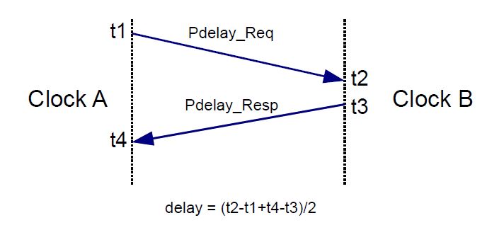
Again notice that this is simpler than the two-step peer delay mechanism. There is no need for a peer delay response follow up message.
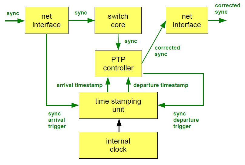
In the case of transparent clocks the difference between one and two step PTP is significant. The diagram below shows a sync message going through a transparent clock.
The transparent clock must intercept the sync message after leaving the switch core and update the correction field based on how long it sat in queues in the transparent clock. Contrast this with a similar diagram of a two-step transparent clock shown in What Are All Of These IEEE 1588 Clock Types?. In the tw0-step version the transparent clock doesn’t need to update the sync message on the fly, but it does need to remember how long it had the sync message for and update the corresponding follow up message. So if you are designing a transparent clock you have to ask yourself if I want to put a lot of effort into the hardware or software. One-step clocks require hardware capable of on-the-fly correction field updates. Two-step clocks require that the software remember the dwell time of a sync message and match it to the corresponding follow up message.
Earlier I made the statement that if you are not building the devices, but just buying them, then it doesn’t matter. But don’t you have to make sure that all the devices in the chain from master to slave use the same number of steps? The answer is no, because all slaves are required by IEEE 1588-2008 to work with either. That was an easy rule to make, since it is only hard to send one-step messages, not receive them. What about the case with a two-step master and a one-step transparent clock? Also no problem. The transparent clock will update the correction field in the sync message, and pass the follow up message through unaltered. The slave will sum the correction fields from both messages, as the standard requires. How about the case with a one-step master and a two-step transparent clock. Still no problem, but a little more work for the transparent clock, since it will have to set the sync step flag to two-step and generate the follow up message.
Isn’t one-step preferred because it uses less network bandwidth? Let’s do a little arithmetic. A follow up messages is 98 bytes for a UDP/IPv4/Ethernet mapping. That’s 784 bits. At a once per second rate that uses less than 0.0001 percent of a gigabit link. Even if there were 100 follow_up messages a second the bandwidth usage is trivial. Even if it were only a 10-BaseT link! For practical purposes assume PTP uses approximately zero bandwidth, whether it is one-step or two-step.
If you have any questions about PTP, don’t hesitate to send me an email at doug.arnold@meinberg-usa.com, or visit our website at www.meinbergglobal.com.


Hi, actually, for 1-step in Peer delay measurement, the time when PDelay_Resp is sent (t3) cannot be sent back to delay requester. There is simply no field or means for that.
so for 1-step P2P mode, the delay calculation should be:
delay = (t4-t1)/2
instead of
delay = (t2-t1+t4-t3)/2
Thanks for the blog post, can you make it so I receive an email every time there is a fresh article?
Hello!
Feel free to use a RSS-Reader like FEEDLY and subscribe to https://blog.meinbergglobal.com/feed/
I do not have any experience with FEEDLY, and so cannot comment on how well it works. But perhaps some reads will want to try it and might find it useful
Hello! Thank you for this very useful blog, and i have a question. In IEEE 1588 document the value of correction field is described as nanoseconds multiplied by 2^16, but in capture packets (from wireshark) i see value of correction field in nanoseconds. Where is truth? Which format i should use in ptp-slave design for calculation offset and mpd?
We all love wireshark. Where would we be without that essential tool? Nevertheless, wireshark does not define PTP, the IEEE does. This is either a miss labeling or a presentation layer simplification by wireshark. Your slave needs to interpret the PTP messages as they are defined in IEEE 1588.
Thank you this blog is very helpful. Regarding the correction field, I understand that devices such as network switches add the accumulated time into this field for Sync and Delay_req messages. How does a slave clock make use of this information considering the formula offset = (t2 + t3 – t1 – t4) /2 and how does a master make use of this information? Is it correct to say that a slave adds the correction field to t1 and the master adds it to (or subtracts it from?) t4?
You have the right idea. However, the slave does all of the calculations, since it is the entity which needs to adjust its clock. The slave adds the correction field to t1, and subtracts it from t4. The correction field is mostly used for transparent clock residence time, in which case it is a positive number.
In one step how to add t3-t2 field in delay resp message (if my PHY is not adding anything is correction field of delay resp)
To implement one step PTP devices, one needs hardare which is capable of generating timestamps and inserting them in message as they are exiting the port. If your hardware does not have that capablility, use two step.
Note that one step and two step devices always work togther if all of the devices correctly implement PTP. Sadly there are non devices out there with incorrect implementations of PTP, so be careful.
Hi,
I have a topology like:
sw1———-sw2———-sw3———–sw4
OC TC TC OC
Master p2p p2p Slave
All are configured in 2-step.
Master-Slave hierarchy is established but time between both is not synced at all.
Hello Keerti,
It’s hard to tell without more information, but let me recommend some things to check. First off, I will assume that these are production PTP devices which work, rather than prototypes which may still have bugs. That leaves configuration problems. I also assume that you have let the network run long enough for the slave to run its PLL, so that we are not simply looking at a transient behavior. Your diagram indicates that the TCs use peer delay. Are the OCs also configured to be peer delay? Are all of the clocks configured for the same timing domain?
It would be worth looking at the PTP messages in detail. You can do this with wireshark, and filtering on ptp. Or you can download PTP Track Hound from the Meinberg Website (https://www.meinbergglobal.com/english/sw/ptp-track-hound.htm). PTP Track Hound works like wireshark, but focused solely on PTP, with more awareness of the protocol.
Good luck,
Doug
Hello
Thanks for the great article.
I have one question regarding One/Two steps.
Is it right to say that two steps is more accurate?
if it’s true, than why is it more accurate? or were is the advantage?
Thanks
Eyal Peleg
Accuracy, of course, depends on the implementation. However in general, neither two-step, not one-step PTP devices are more accurate than the other. The advantage of two-step, for implementors, is that the device has simpler networking hardware. It only needs to timestamp PTP event message, and not insert the timestamp into the message as it is leaving. The advantage of one-step clocks is simpler software. They do not have to associate sync and Follow_up message with each other, or delay_Request and delay_response messages. The advantage of one-step is especially important for Transparent Clocks. They can change the correcton field of messages that they are timestamping and then foget them. A two step transparent clock has to save the correction field value, wait for the corresponding follow_up or Delay_repsonse message and change the correction fields of those messages.
Does the slave need to embed the timestamp in the delay_request message to achieve phase accuracy for the profile G8275.2?
The timestamp in the delay_request is not needed as long as the slave remembers the delay request departure timestamp for calculating delay and offset after the delay_response arrives.
The timestamp field is included in the delay_request so that the message will be the same size as the sync message for purposes of propagation delay symmetry.
your blog is very wonderful. Thank you.
“What about the case with a two-step master and a one-step transparent clock? Also no problem. The transparent clock will update the correction field in the sync message, and pass the follow up message through unaltered. ”
Actually, I’m a little confused about this: my understand is that if a one-step transparent clock, it will fill the origintimestamp field by HW by setting HWTSTAMP_TX_ONESTEP_SYNC option?
If so, when to calculate the correction field and how the HW know to fill the correction field?
Could you please help to point my error out?
A one step transparent clock timestamps the Sync message upon arrival and also as it departs. The Sync message residence time is the departure time – arrival time. With end-to-end networks this residence time is added to the correction field. With peer-delay networks the residence time plus the upstream link delay is added to the correction field. In either case a one-step transparent clock updates the correction field as it is transmitting the Sync message, or it updates it before transmitting with a know delay to transmission built into the residence time calculation. Note also that PTP ports in the slave state are required to add the correction fields of the Sync and Follow_Up message (if it gets a Follow_up), so transparent clocks can update either message when they are both present.
What the setting is called on your transparent clock varies from manufacturer to another, but “HWTSTAMP_TX_SYNC” looks promising for turning on one-step timing in a transparent clock.
Also, i think it’s impossible to fill the origintiemstamp field for a transparent clock, bcz the transparent clock will not be involved into time sync, right?
And HW actually doesn’t have enough information to know it is a transparent clock, so it doesn’t know it needs to change the correction field, right?
I’m looking forward to your reply. Thanks in advance!
See response to previous comment.